
phone icon
Phone
envelope icon
Mail
1/3
Dimensioning and Design

A few points have to be considered when dimensioning precision-milled precision profile strips. For precise positioning during milling, it is necessary to place the strip against a lateral guide. The contact side is the reference side for the dimensioning. Other dimensioning variants are possible by arrangement. All the dimensions result from this positioning as described below.
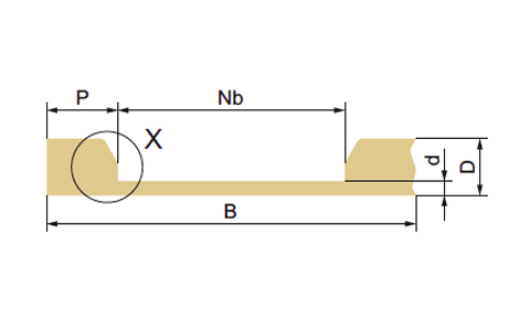
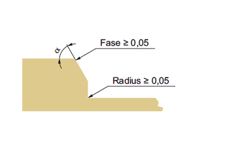
Drawing 1
Milling widths (Nb) are determined by the milling tool. The minimum tolerance is ± 0.02 mm. Position dimension (P) is measured from the reference side. Thicknesses are defined by the remaining strip thickness.
Detail X
You can obtain more detailed information upon request or following the provision of samples

When designing precision profile strips, we recommend taking the following into account to ensure cost-effective production and to facilitate handling:

• During milling, a cutting burr is produced, depending on the alloy and the milling geometry. To reduce or prevent this burr, a flank angle of ≤ 60°, or alternatively a flank angle of up to 88° and a chamfer or radius of ≥ 0.05 mm, is required on the milling flanks (see Drawing 1, Detail X)!

Other geometries are available by arrangement.

A member of the KEMPER Group